Stop Motion Puppet
Sun, Oct 23rd, 2022 - Project Status: Closed

It has been well over a year since I released my first album - Push Me Away. I was a bit burned out from that endeavor, so I put music on-hold for a while. So, what have I been doing in my spare time? Many things, just not music. For some reason I decided to start a new hobby.
Motion Activated Toy
Sun, Oct 3rd, 2021 - Project Status: Closed

This project will show you how to activate a battery operated toy when motion is sensed in front of it. Use it to turn on a toy when trick-or-treaters approach your front door. Or use it as a "guard" to activate a loud toy or siren when someone walks into a room. The circuit is designed to turn off the toy after approximately 25 seconds. This simple circuit is designed to connect to low-power battery operated devices, not to devices connected to household voltages.
PIC18F45K22 External Interrupt
Mon, Aug 7th, 2017 - Project Status: Closed

This article describes how to use an external interrupt on a PIC18F45K22 microcontroller. In my previous PIC18F45K22 article, I described how to use the Timer0 interrupt. I explained that when Timer0 register overflowed, the timer's interrupt flag is set causing the program flow to switch from main to the interrupt service routine, or ISR. This allows a block of code that is not in the main program loop to be executed at periodic intervals. This interval is software controlled.
PIC18F45K22 Timer0 Interrupt
Wed, Jul 26th, 2017 - Project Status: Closed

This project describes how to program a PIC18F45K22 microcontroller to use the Timer0 module and the Timer0 Interrupt. With regards to PIC18 programming, why is this useful? Consider this real-world situation. You are working on a task and periodically, let's say every hour, you are required to update your boss on your progress. You set a timer for one hour so you do not forget to update your boss.
PIC18F45K22 Analog-to-Digital Conversion
Fri, Jul 21st, 2017 - Project Status: Closed

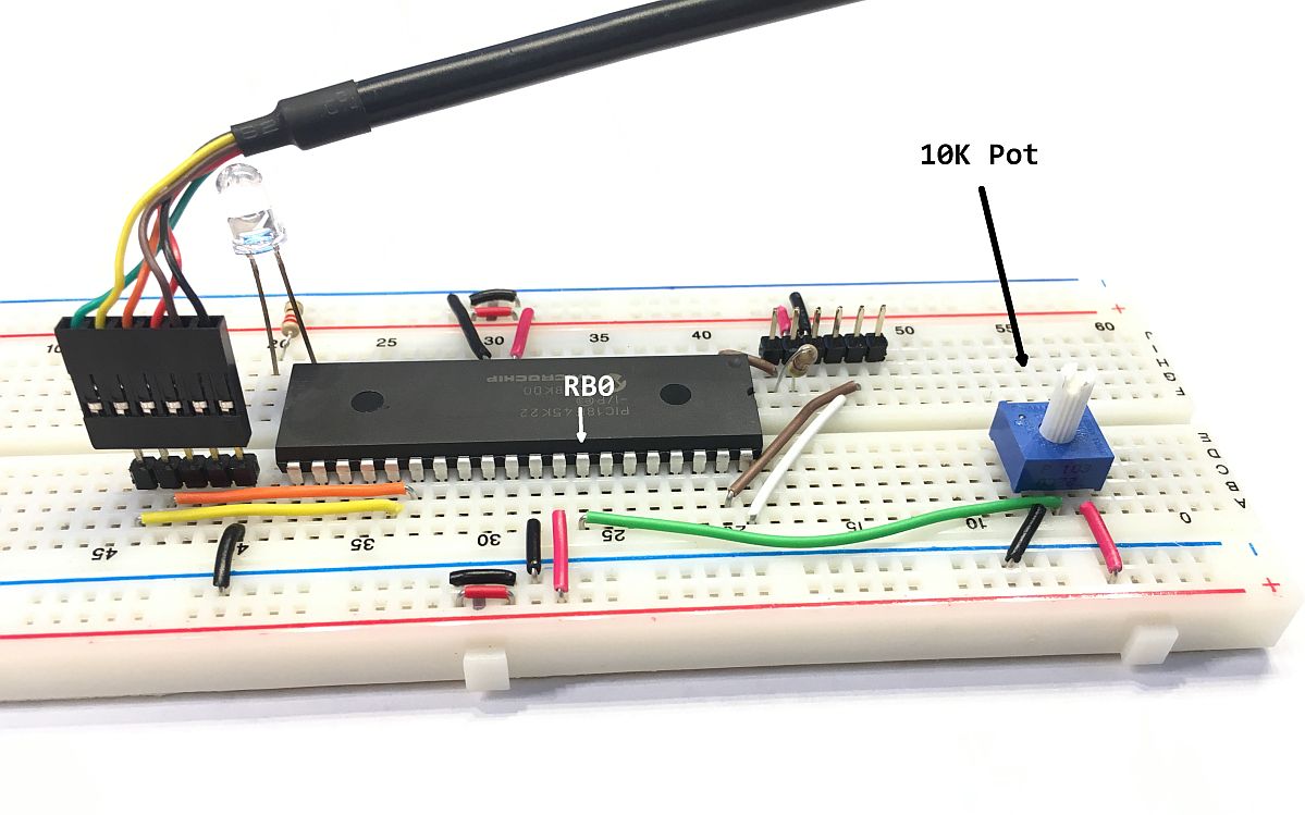
This article will describe the steps necessary to program a PIC18F45K22 microcontroller to perform analog-to-digital conversions. Computers are digital devices that perform binary input and output by design. A bit is either 0 or 1, a pin is eiher high or low, 0 volts or 5 volts. Reading a varying voltage, a voltage in the range of the system minimum and maximum requires specialized hardware called an analog-to-digital converter, or ADC. The PIC18F45K22 contains this capability as do many microcontrollers.
The resolution of the PIC18F45K22 ADC module is 10 bit.
PIC18F45K22 Serial Port Communication
Sun, Jul 16th, 2017 - Project Status: Closed

This article describes how to setup and program a PIC18F45K22 microcontroller for serial communication. At project completion, for every byte the PIC micro receives in it's serial port buffer, it will transmit the same value out the serial port. Learning to program your microcontroller to communicate using the serial port, will open the door to many fun and interesting projects. For example, it is possible to have your microcontroller send messages to a WIFI micro, such as the ESP8266, using the serial port. This allows your microcontroller to communicate with the world using the internet.
The PIC18F45K22 contains two peripheral modules for serial I/O called the Enhanced Universal Synchronous Asynchronous Receiver Transmitter (EUSART).
An Introduction to the PIC18F45K22 Micro
Thu, Jan 26th, 2017 - Project Status: Closed

If you want to start building your own Internet of things (IOT) devices, then you are going to need to learn how to program a microcontroller. Don't worry, these days it's not necessary to learn to code in assembly language to program a microcontroller. If you are familiar with a C-based language, then you should be fine. The Arduino is a good starting point, because it is relatively easy to learn and not too expensive. However, after you create your cool Arduino-based gadget and want to start a new project, you will need to purchase another Arduino or disassemble your cool gadget and re-use your existing Arduino.
PIC Microcontroller Example
Mon, Jan 19th, 2015 - Project Status: Closed

Programming micro-controllers can be a very rewarding hobby. I have been programming mid-level MCU's like the Arduino, Netduino, and the BX24 for several years now. These MCU's are relatively easy to program, which makes them a great choice to prototype your next great idea. However, the cost of these MCU's don't make them practical for building multiple permanent gadgets. It's more cost effective to use a lower level MCU since these cost much less.
Camera Shutter Timer - At Last
Mon, Jun 6th, 2011 - Project Status: Open

Last year, I decided to make a shutter timer for my vintage cameras. Just as quick as I came up with the project idea, it was put on the back-burner for various reasons. Well, it's half way into the following year and I have finally had time to work on this project. Why build a camera shutter timer? You can read the details here, but in short, to save money.
Camera Shutter Tester
Sun, Mar 28th, 2010 - Project Status: Open

I collect vintage cameras. Due to their age and years of non-use many of the shutters are inaccurate. I have sent some out for CLA or repair but this can be quite costly. Sending them all out for repair is currently not an option. If the shutter is consistently slow but not intermittently slow or erratic, I can compensate for the inaccuracy by adjusting the shutter speed, aperture or film speed.
Horse Chestnut Tree?
Sat, Jan 23rd, 2010 - Project Status: Closed

Along the creek that borders my dad's property are a few Horsechestnut trees, at least I think they are Horsechestnut trees. I was reminded of this during a family visit last Thanksgiving when all the kids decided to play down at the creek. Like good parents, we followed them down to the water and hoped they didn't get hurt. I noticed the large Horsechestnut seeds at our feet most of which were out of their seedpod. The seed outside the seedpod is shiny brown, relatively hard and slightly larger than an extra large chicken egg.