This article describes how to use an external interrupt on a PIC18F45K22 microcontroller. In my previous PIC18F45K22 article, I described how to use the Timer0 interrupt. I explained that when Timer0 register overflowed, the timer's interrupt flag is set causing the program flow to switch from main to the interrupt service routine, or ISR. This allows a block of code that is not in the main program loop to be executed at periodic intervals. This interval is software controlled. So, what is the benefit of using an external interrupt instead of the Timer0 interrupt? There are a couple of good reasons to use an external interrupt. First, by using an external interrupt, something other than the microcontroller controls when the interrupt flag is set and the ISR code is executed. This external event can be a sensor signal, switch, or even another microcontroller. The second reason to use an external interrupt is because an external interrupt can waken the PIC18F45K22 when it is idle or in sleep mode. Timer0 shuts down during sleep mode so it can not be used to waken the microcontroller. For your PIC project, you do not need to choose one or the other interrupt type, as both can be used in the same PIC program. This article continues from my previous artcle titled PIC18F45K22 Timer0 Interrupt. I will refer to information that is specified in the PIC18F45K22 datasheet. Here is a link to this datasheet for your reference.
PIC18F45K22 Datasheet
Just like all my other PIC18F45K22 microcontroller projects, for this project I will use the C programming language to program my PIC. The compiler I am using is Microchip's XC8 compiler version 1.35. Programming the PIC to use an external interrupt is relatively easy. There are three registers we need to be concerned with - INTCON, INTCON2, and INTCON3. In the INTCON register we must set bits 6 and 7, Global Interrupt Enable (GIE) and Peripheral Interrupt Enable (PEIE) respectively.
    /* Enable Global Interrupts GIE, bit 7

     * Enable Peripheral Interrupts, bit 6 */

    INTCON = 0b11000000;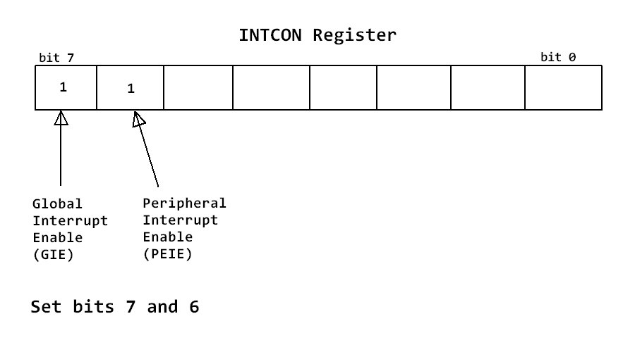
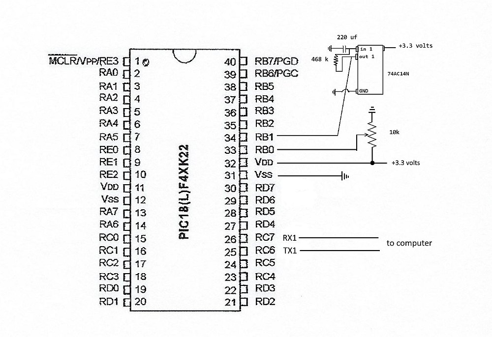
On the PIC18F45K22 there are three external interrupts to choose from, INT0, INT1, and INT2. INT0 is associated with RB0, pin 33. Since I am already using RB0 for ADC (as explained in previous article), I will use RB1, pin 34 which is associated with INT1. I would like the external interrupt to be triggered when pin 34 transitions from 0 volts to 3.2 volts which is the PIC's system voltage for this project. This is configured by setting bit 5 of the INTCON2 register which is named INTEDG1.
    /*Set INT1 to trigger on rising edge*/

    INTCON2bits.INTEDG1 = 1;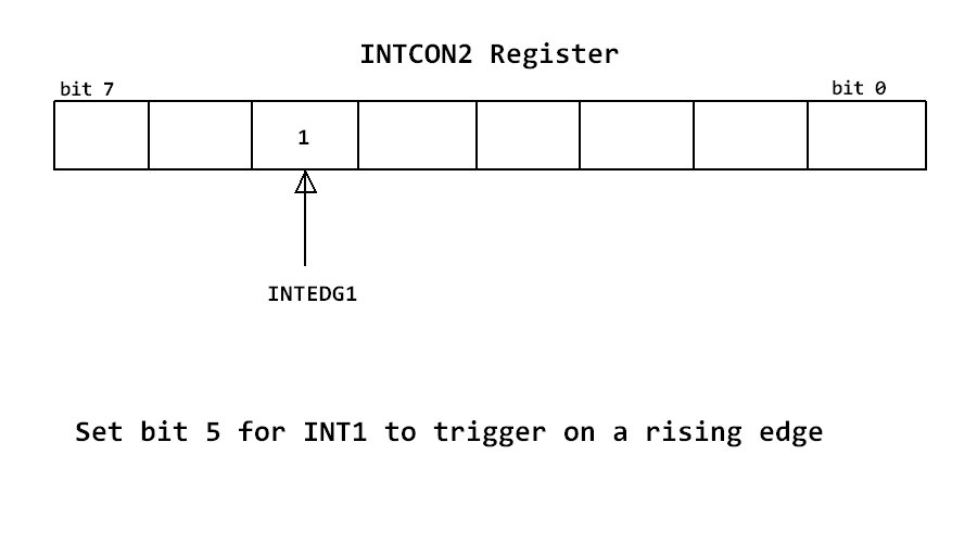
In the INTCON3 register there are two bits that must be configured. Setting bit 3, INT1IE, enables INT1 and clearing bit 0, INT1IF, clears the INT1 interrupt flag. This flag must also be cleared in the ISR so that the program can continue to be informed of INT1 events after an interrupt has been triggered.
    /*Clear INT1 interrupt flag*/

    INTCON3bits.INT1IF = 0;


    /*Enable external interrupt INT1*/

    INTCON3bits.INT1E = 1;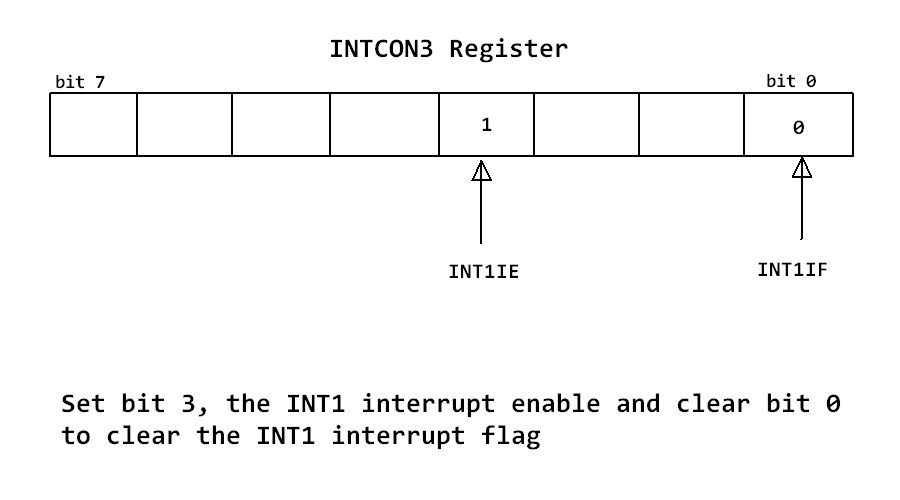
The code in the ISR related to INT1 is slightly more simple than the code for Timer0 since we do not need to load values in TMR0H and TMR0L. In the ISR, I simply call the txVoltage function and clear the INT1 interrupt flag.
    // If external interrupt has occurred

    if(INTCON3bits.INT1IF == 1){

        txVoltage(); // transmit voltage out serial port

        INTCON3bits.INT1IF = 0; // clear INT1 interrupt flag

    }
For this project I will use a delay circuit connected to RB1 (pin 34) of the PIC to trigger the external interrupt. The circuit is composed of a Schmitt Trigger, 468 kilo ohm resistor, and a 220 micro fahrad capacitor. The RC values used give a delay (0 volts)of approximately 60 seconds followed by a high-time (3.2 volts) of approximately 60 seconds. This means the cycle time is approximately 120 seconds. Therefore, the current voltage value will be transmitted out the serial port every 120 seconds. As stated, above, any type of circuit that periodically sends high and low signals can be used to trigger the external interrupt. I chose the aforementioned delay circuit because it is easy to implement and the 74AC14N Schmitt Trigger works with the 3.2 volts that this project is using. If you do not have a 74AC14N, I believe that there are some 555 timers which can also be run at 3.2 volts and be configured as a delay circuit. If you do not have either ICs, simply use a switch connected to the power bus to send high signals to pin 34. Be sure to use a pull-down resistor to pull the voltage to zero volts when the switch is not made. Be creative. There are many possible circuits or items that can be used to trigger the interrupt.
The following is the full code of main.c for this project.
/***********************************************

 * Project Name: PIC18_Ext_INT

 * Author: Frank Mock, August 2017

 * File Name: main.c

 * Microcontroller used: PIC18F45K22

 * Compiler used is XC8 VERSION 1.35

 * Description: The main loop simply reads the value of the ADC output, when an

 *              external interrupt occurs, the code in the ISR will be executed.

 *              The ISR sends the current voltage value out the serial port

 *              (USART1).

 * Serial Port Settings: Baud rate 115200, 8 bit, no flow control, no stop bit

 ****************************/

#include< xc.h >

#include< stdio.h > // For sprintf to convert int to string

#include< plib\usart.h >

#include< plib\adc.h >

// Oscillator Selection bits (Internal oscillator block)

#pragma config FOSC = INTIO67

// MCLR Pin Enable bit (MCLR pin enabled, RE3 input pin disabled)

#pragma config MCLRE = EXTMCLR

// Watchdog Timer Enable bits (Watchdog timer is always disabled)

#pragma config WDTEN = OFF


#define _XTAL_FREQ 16000000  //speed of the internal oscillator


unsigned char c; // will hold rx value

const float VOLTAGE = 3.291; // system voltage

float volts; // to hold the voltage

char str[256]; //buffer to hold string


// Function prototypes

void SetUpClock();// setup internal oscillator

void interrupt isr(void); //UART receive interrupt handler

void delay_seconds(unsigned char s); //Creates delay in seconds

void FlashLEDs(); //Flashes an LED at one second intervals

float readVoltage(); // Read the ADC, convert and assign to volts

void txVoltage(); // Transmit voltage out the serial port


int main(){

    SetUpClock(); //internal clock set to 16MHz


    /*Port setup for the LED*/

    ANSELD = 0; //Configure PORTD as digital

    TRISD = 0; //Configure PORTD as output

    PORTD = 0b00000000; //initial state - PORTD all off


    /*Port setup for the ADC*/

    ANSELB = 0b00000001; // Configure pin33 RB0 (AN12) as analog

    TRISB = 0b00000011; // Set RB0 and RB1 as an input


    /*Configure the A/D converter*/

    OpenADC(ADC_FOSC_2 & ADC_RIGHT_JUST & ADC_12_TAD,

            ADC_CH12 & ADC_INT_OFF,

            ADC_TRIG_CTMU & ADC_REF_VDD_VDD & ADC_REF_VDD_VSS);

     /*

     * According to page 268 of the data sheet, TRIS control bits of

     * RX and TX should be set to 1. USART will automatically reconfigure

     * them from input to output as necessary */

    TRISCbits.RC6 = 1;

    TRISCbits.RC7 = 1;


    //analog PORTC ports may interfere with serial port receive

    ANSELC = 0X00; //Make all PORTC pins digital

    RCONbits.IPEN = 0; //Disable using interrupt priority


    /* Enable Global Interrupts GIE, bit 7

     * Enable Peripheral Interrupts, bit 6 */

    INTCON = 0b11000000;


    /*Set INT1 to trigger on rising edge*/

    INTCON2bits.INTEDG1 = 1;


    /*Clear INT1 interrupt flag*/

    INTCON3bits.INT1IF = 0;


    /*Enable external interrupt INT1*/

    INTCON3bits.INT1E = 1;


    Close1USART();  //turn off USART if was previously on


    //configure USART

    Open1USART(USART_TX_INT_OFF &

               USART_RX_INT_ON &

               USART_ASYNCH_MODE &

               USART_EIGHT_BIT &

               USART_CONT_RX &

               USART_BRGH_HIGH,

               8);//8 = x. Calculated x using 16(x + 1) = Fosc / Baud Rate

                 // This gave me a 115,200 baud rate


    for(;;){

        volts = readVoltage(); // ADC

    }

}


/*IRCF<2:0> Set Up Internal RC Oscillator Frequency Select bits

 * 111 = HFINTOSC - (16 MHz) SEE PAGE 32 OF DATASHEET

 */

void SetUpClock(){

    OSCCONbits.IRCF0 = 1;

    OSCCONbits.IRCF1 = 1;

    OSCCONbits.IRCF2 = 1;

}


//UART receive interrupt handler

void interrupt isr(void){

    //The serial port has received a byte

    if((PIR1bits.RC1IF == 1)&&(PIE1bits.RC1IE == 1)){

        // The serial port has received a byte

        c = Read1USART();

        // Transmit what was received out the serial port

        Write1USART(c);

        //Clear ISR flag

        PIR1bits.RC1IF = 0;

    }


    // If external interrupt has occurred

    if(INTCON3bits.INT1IF == 1){

        txVoltage(); // transmit voltage out serial port

        INTCON3bits.INT1IF = 0; // clear INT1 interrupt flag

    }

}


/* Creates delay in seconds

 * parameter s is the number of seconds */

void delay_seconds(unsigned char s){

    unsigned char i,j;

    for(i = 0; i < s; i++){

        for(j = 0; j < 100; j++)

            __delay_ms(10);

    }

}


//Flashes an LED at one second intervals

void FlashLEDs(){

    for(int i = 0;i < 2; i++){

        PORTDbits.RD1 = 1;  //LED 1 ON

        delay_seconds(1);

        PORTDbits.RD1 = 0;  //LED 1 OFF

        delay_seconds(1);

    }

}

// Capture and save ADC value

float readVoltage(){

    SelChanConvADC(ADC_CH12); // Select CH12 and start the conversion

    while(BusyADC()); // Wait for A/D conversion to complete

    int v = ReadADC(); // Read converted data

    return v * VOLTAGE/1024; // convert to volts

}

// Transmit current voltage value out serial port

void txVoltage(){

    sprintf(str, "Volts = %f\r\n", volts); // convert to string

    putrs1USART(str); // write the string out the serial port

}
I hope this article has inspired you to try and program a PIC micro to use an external interrupt. As you can see, programming a PIC to do so is relatively simple. External interrupts allow events outside the PIC to play a part in what happens internally. Once you learn this skill, I am sure you will find many ways to interface circuits with a PIC as a way to make interesting projects. Please read my other PIC articles to learn other PIC18F45K22 programming skills using the C language. I welcome your questions or comments. Just use my contacts page to contact me. That is all for now, thank you.

