This project describes how to program a PIC18F45K22 microcontroller to use the Timer0 module and the Timer0 Interrupt. With regards to PIC18 programming, why is this useful? Consider this real-world situation. You are working on a task and periodically, let's say every hour, you are required to update your boss on your progress. You set a timer for one hour so you do not forget to update your boss. This way you can concentrate on your work and when the timer interrupts you, you know it's time to stop what you are doing and inform your boss on your progress. After informing your boss, you continue with your work. As in the analogy, setting the PIC18 timer allows the main loop of your program to execute until it is interrupted. At this time it will execute another chunk of code and when finished, return to the main program loop. In this project, the main program loop will read a voltage using the PIC's ADC module. When the timer overflows and causes the interrupt flag to be set, the chunk of code in the interrupt service routine (ISR) related to the timer interrupt will be executed. The ISR will simply transmit the current voltage value out the serial port and re-set the timer. When finished, it will go back to executing the code in the main program loop. This project continues where my previous project titled, PIC18F45K22 Analog-to-Digital Conversion finished. Please refer to the previous article for information on setting up the PIC to do serial port I/O and ADC. In this article, I will refer to information that is specified in the PIC18F45K22 datasheet. Here is a link to this datasheet for your reference.
PIC18F45K22 Datasheet
The PIC18F45K22 has multiple timer modules available. For this project I use Timer0. In my previous PIC18 projects, when using peripheral modules such as the ADC or USART, I used some helper functions from the peripheral library that came with the XC8 C compiler (compiler version 1.35). These library functions abstracted away some of the more gory programming details and made the modules easier to use. Though the Timer0 module has functions in the peripheral library, for this project I will not use them. This is because, the Timer0 module and it's related interrupt are easy to use since there are only a few registers to configure. Two of these 8-bit registers are INTCON and T0CON, which are associated with interrupt and timer control respectively. The other two registers are TMR0H and TMR0L which are the registers that hold the timer high and low values respectively.
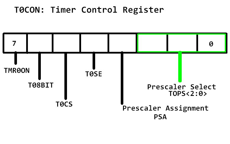
First I will explain the T0CON register. To setup Timer0 you simply set or clear it's associated bits of T0CON as necessary. The following is an explanation of what each bit of this register controls. To follow along, you may wish to refer to section 11.1 on page 159 of the PIC18F45K22 datasheet which covers the Timer0 Control register definition. Bit 7, TMR0ON, enables or disables Timer0. Setting this bit enables the timer and clearing it stops the timer. Bit 6, T08BIT, configures the timer in either 8-bit mode or 16-bit mode. The mode you select depends on the required timer interval. For very short time intervals, such as 5 milliseconds, 8-bit will suffice. For longer time intervals, 16-bit mode is more appropriate. In case you do not fully understand, I want to briefly explain how a timer works on the PIC18. A timer can simply be thought of as a counter that advances with each time period. Notice, that I did not say for each clock cycle, I will explain why later. Each counter is finite and has a maximum value related to the number of bits it uses to count. An 8-bit counter has a maximum value of 255 or 0xff and a 16-bit counter has a maximum value of 65535 or 0xffff. Since each counter starts counting at zero, they count for one more time period than their maximum value before overflowing. 256 time periods for 8-bit and 65536 for 16-bit. When the counter overflows it starts counting at zero again. It is like an odometer in a car. Bit 5 of T0CON is named T0CS and selects which instruction clock to use for the timer. Setting this bit configures the Timer0 to transition on T0CKI pin and clearing this bit configures Timer0 to use the internal clock. Bit 4, T0SE, is the source edge select bit. Setting this bit advances the timer on a high-to-low transisition and clearing it advances the timer on a low-to-high transistion. Bit 3, PSA is the prescaler assignment bit. By using a prescaler, the timer can be slowed down so it does not overflow so quickly. The prescaler is essentially a shift register. Setting this bit disables the prescaler and clearing this bit enables the prescaler. Bits 2 - 0, TOPS < 2:0 > are the Timer0 prescaler select bits. Since there are 3 bits used, bits 0 - 2, there are 8 different prescaler values. The different prescaler values slow the timer down by different powers of two. For this project, I will use the maximum value of 1:256.
Adding to the code from the aforementioned PIC18F45K22 project, the following statement enables Timer0 in 16-bit mode using the internal clock.
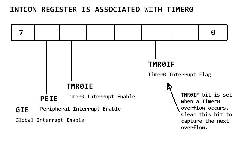
T0CON = 0b10000111; // Configure Timer0The next register I will discuss is INTCON, which is the regsiter used to configure interrupts on the PIC18. Bit 5 of the INTCON register is named TMR0IE. Setting this bit enables the Timer0 interrupt, so that when the timer overflows the interrupt flag (bit 2) is set and a TMR0 interrupt is generated. This causes the code execution to be switched to the interrupt service routine, or ISR. Since Timer0 is a peripheral, you must also set bit 6 which is the peripheral enable bit, or PEIE and bit 7 which is the gloal interrupt enable bit, or GIE.
The following statement sets GIE, PEIE, and TMR0IE.
/* Enable Global Interrupts GIE, bit 7

* Enable Peripheral Interrupts, bit 6

* Enable Timer0 interrupt, bit 5

* Clear TMR0 Interrupt flag, bit 2 */

INTCON = 0b11100000;
After the Timer interrupt is triggered, you must clear bit 2 of the INTCON register if you want to catch the next time a timer overflow occurs. Do this in the ISR.
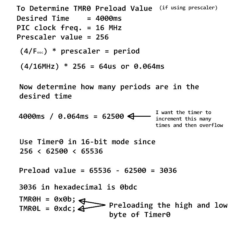
INTCONbits.TMR0IF = 0; // clear Timer0 interrupt flagYou might be wondering how to set the timer to a specific time interval, such as 500 ms or 1 sec. This is where working with the PIC timer gets fun. For starters, it is important to know that PIC code executes at 1/4 the oscillator clock. For example, for this project I have chosen to use the 16 MHz internal oscillator of the PIC. Therefore, the program execution frequency is acutally 16/4 MHz or 4 MHz. Armed with this information, I now know that the clock period is 1/4 MHz or .25 microseconds, or us. This means that if not using a prescaler, Timer0 increments every .25us. To slow things down, I will only increment the clock on ever 256th time period by using the prescaler set to 1:256. My adjusted time period becomes .25us * 256 which is 64us or .064ms. In this project, I want the timer to overflow every 4 seconds. 4000ms / .064ms = 62,500. This means I want Timer0 to increment 62,500 times and then overflow. Since this number is much larger than the maximum value of an 8-bit register, I must use Timer0 in 16-bit mode since 2^16 = 65,536 > 62,500. Additionaly, since I only want Timer0 to increment 62,500 times and not 65,536, I must preload the timer with the difference of these two numbers which is 3036 or 0xbdc in hexadecimal. Since the PIC18F45K22 has an 8-bit data bus, the PIC uses two 8-bit registers, TMR0H and TMR0L, to count in 16-bit mode. The preload value goes in these two registers. 0x0b goes into TMR0H and 0xdc goes into TMR0L. If it is still not clear how to set the timer to achieve a desired time, then maybe the following image will help. It shows the steps I just described.
 The following code goes into the main function outside the main loop and also inside the ISR.
TMR0H = 0x0b; // Pre-load TMR0 upper byte

TMR0L = 0xdc; // Pre-load TMR0 lower byte
As explained above, the main loop of the program for this project will simply read a voltage. The voltage will be read on pin 33, RB0, which has been setup as an analog input. Please refer to my last project to learn about using the analog-to-digital, or ADC module on a PIC18. One difference between the last project and this one as far as the ADC goes, is that I put the ADC code in a function I named readVoltage. The following is the main loop of this program.
for(;;){

    volts = readVoltage(); // ADC

}
Here is the readVoltage function:
float readVoltage(){

    SelChanConvADC(ADC_CH12); // Select CH12 and start the conversion

    while(BusyADC()); // Wait for A/D conversion to complete

    int v = ReadADC(); // Read converted data

    return v * VOLTAGE/1024; // convert to volts

}
I added the following code to the ISR from the previous project. This code determines wether a Timer0 interrupt occured and if so, transmits the current voltage value, re-loads the upper and lower byte of Timer0 with the preload value, and clears the Timer0 interrupt flag.
    // If Timer0 Interrupt is triggered

    if(INTCONbits.TMR0IF == 1){

        txVoltage(); // transmit voltage out serial port

        TMR0H = 0x0b; // re-load TMR0H

        TMR0L = 0xdc; // re-load TMR0L

        INTCONbits.TMR0IF = 0; // clear Timer0 interrupt flag

    }
By setting the PIC18 timer and it's related interrupt, it allows the main code loop to continually execute and perform a subtask at preset intervals. This proves to be an extremely useful cabability. Imagine a robot that needs to report back to a base station it's current position at regular intervals. This would be one use of a timer interrupt. Or perhaps a data logger that needs to send the contents of it's data buffer to a server every hour. There are many possible reasons to use a timer interrupt. I hope this article proves to be useful. Feel free to contact me via my contacts page with any questions or comments. Next is the complete code. Note that there are some functions in the code that do not pertain to this project, such as the flashLEDs function, but are included since this is just one part of an on-going PIC18F45K22 series. Please read my other PIC18F45K22 articles if you enjoyed this one.
/***********************************************

 * Project Name: PIC18-Timer0-INT

 * Author: Frank Mock, July 2017

 * File Name: main.c

 * Microcontroller used: PIC18F45K22

 * Compiler used is XC8 VERSION 1.35

 * Description: In main loop, the ADC continually reads a voltage.

 *              Timer0 will be configured to overflow and trigger the timer

 *              interrupt every 4 seconds. When this occurs, the ISR will send

 *              the current voltage value out the serial port (USART1)

 * Serial Port Settings: Baud rate 115200, 8 bit, no flow control, no stop bit

 ****************************/

#include< xc.h >

#include< stdio.h > // For sprintf to convert int to string

#include< plib\usart.h >

#include < plib\adc.h >


// Oscillator Selection bits (Internal oscillator block)

#pragma config FOSC = INTIO67

// MCLR Pin Enable bit (MCLR pin enabled, RE3 input pin disabled)

#pragma config MCLRE = EXTMCLR

// Watchdog Timer Enable bits (Watchdog timer is always disabled)

#pragma config WDTEN = OFF


#define _XTAL_FREQ 16000000  //speed of the internal oscillator


unsigned char c; // will hold rx value

const float VOLTAGE = 3.291; // system voltage

float volts; // to hold the voltage

char str[256]; //buffer to hold string


// Function prototypes

void SetUpClock();// setup internal oscillator

void interrupt isr(void); // Interrupt handler

void delay_seconds(unsigned char s); //Creates delay in seconds

void FlashLEDs(); //Flashes an LED at one second intervals

float readVoltage(); // Read the ADC, convert and assign to volts

void txVoltage(); // Transmit voltage out the serial port


int main(){

    SetUpClock(); //internal clock set to 16MHz


    /*Port setup for the LED*/

    ANSELD = 0; //Configure PORTD as digital

    TRISD = 0; //Configure PORTD as output

    PORTD = 0b00000000; //initial state - PORTD all off


    /*Port setup for the ADC*/

    ANSELB = 0b00000001; // Configure pin33 RB0 (AN12) as analog

    TRISB = 0b00000001; // Set RB0 as an input


    /*Configure the A/D converter*/

    OpenADC(ADC_FOSC_2 & ADC_RIGHT_JUST & ADC_12_TAD,

            ADC_CH12 & ADC_INT_OFF,

            ADC_TRIG_CTMU & ADC_REF_VDD_VDD & ADC_REF_VDD_VSS);

     /*

     * According to page 268 of the data sheet, TRIS control bits of

     * RX and TX should be set to 1. USART will automatically reconfigure

     * them from input to output as necessary */

    TRISCbits.RC6 = 1;

    TRISCbits.RC7 = 1;


    //analog PORTC ports may interfere with serial port receive

    ANSELC = 0X00; //Make all PORTC pins digital

    RCONbits.IPEN = 0; //Disable using interrupt priority


    T0CON = 0b10000111; // Configure Timer0


    /* Enable Global Interrupts GIE, bit 7

     * Enable Peripheral Interrupts, bit 6

     * Enable Timer0 interrupt, bit 5

     * Clear TMR0 Interrupt flag, bit 2 */

    INTCON = 0b11100000;


    TMR0H = 0x0b; // Pre-load TMR0 upper byte

    TMR0L = 0xdc; // Pre-load TMR0 lower byte


    Close1USART();  //turn off USART if it was previously on


    //configure USART

    Open1USART(USART_TX_INT_OFF &

               USART_RX_INT_ON &

               USART_ASYNCH_MODE &

               USART_EIGHT_BIT &

               USART_CONT_RX &

               USART_BRGH_HIGH,

               8);//8 = x. Calculated x using 16(x + 1) = Fosc / Baud Rate

                 // This gave me a 115,200 baud rate


    for(;;){

        volts = readVoltage(); // ADC

    }

}


/*IRCF<2:0> Set Up Internal RC Oscillator Frequency Select bits

 * 111 = HFINTOSC - (16 MHz) SEE PAGE 32 OF DATASHEET

 */

void SetUpClock(){

    OSCCONbits.IRCF0 = 1;

    OSCCONbits.IRCF1 = 1;

    OSCCONbits.IRCF2 = 1;

}


// Interrupt handler

void interrupt isr(void){

    // If the serial port has received a byte

    if((PIR1bits.RC1IF == 1)&&(PIE1bits.RC1IE == 1)){

        // Read byte and assign to c

        c = Read1USART();

        // Transmit what was received out the serial port

        Write1USART(c);

        //Clear ISR flag

        PIR1bits.RC1IF = 0;

    }


    // If Timer0 Interrupt is triggered

    if(INTCONbits.TMR0IF == 1){

        txVoltage(); // transmit voltage out serial port

        TMR0H = 0x0b; // re-load TMR0H

        TMR0L = 0xdc; // re-load TMR0L

        INTCONbits.TMR0IF = 0; // clear Timer0 interrupt flag

    }

}


/* Creates delay in seconds

 * parameter s is the number of seconds */

void delay_seconds(unsigned char s){

    unsigned char i,j;

    for(i = 0; i < s; i++){

        for(j = 0; j < 100; j++)

            __delay_ms(10);

    }

}


//Flashes an LED at one second intervals

void FlashLEDs(){

    for(int i = 0;i < 2; i++){

        PORTDbits.RD1 = 1;  //LED 1 ON

        delay_seconds(1);

        PORTDbits.RD1 = 0;  //LED 1 OFF

        delay_seconds(1);

    }

}


//Use the ADC to read a voltage on ADC_CH12

float readVoltage(){

    SelChanConvADC(ADC_CH12); // Select CH12 and start the conversion

    while(BusyADC()); // Wait for A/D conversion to complete

    int v = ReadADC(); // Read converted data

    return v * VOLTAGE/1024; // convert to volts

}


//Transmit the current voltage value

void txVoltage(){

    sprintf(str, "Volts = %f\r\n", volts); // convert to string

    putrs1USART(str); // write the string out the serial port

}
The above code can be viewed and downloaded from my GitHub code repositoryGo to GitHub
