This article will describe the steps necessary to program a PIC18F45K22 microcontroller to perform analog-to-digital conversions. Computers are digital devices that perform binary input and output by design. A bit is either 0 or 1, a pin is eiher high or low, 0 volts or 5 volts. Reading a varying voltage, a voltage in the range of the system minimum and maximum requires specialized hardware called an analog-to-digital converter, or ADC. The PIC18F45K22 contains this capability as do many microcontrollers.
The resolution of the PIC18F45K22 ADC module is 10 bit. Therefore, an instance of the analog input signal to the ADC will result in an integer from 0 to 1024. This value can then be converted to the necessary units, such as volts as in this project. Many sensors such as temperature or pressure sensors output a varying voltage. Some of these signals require the voltage to be amplified so that the microcontroller can accurately read it. For this article, the microcontroller will simply read a varying voltage from a potentiometer. No amplifying circuit will be necessary. This project will continue from the point where my last project titled, PIC18F45K22 Serial Port Communication ended. The voltage read by the ADC will be converted to a string and then be sent out the serial port. Please refer to the previous article for information on setting up the PIC to do serial I/O. In this article, I will refer to information that is specified in the PIC18F45K22 datasheet. Here is a link to this datasheet for your reference.
PIC18F45K22 Datasheet
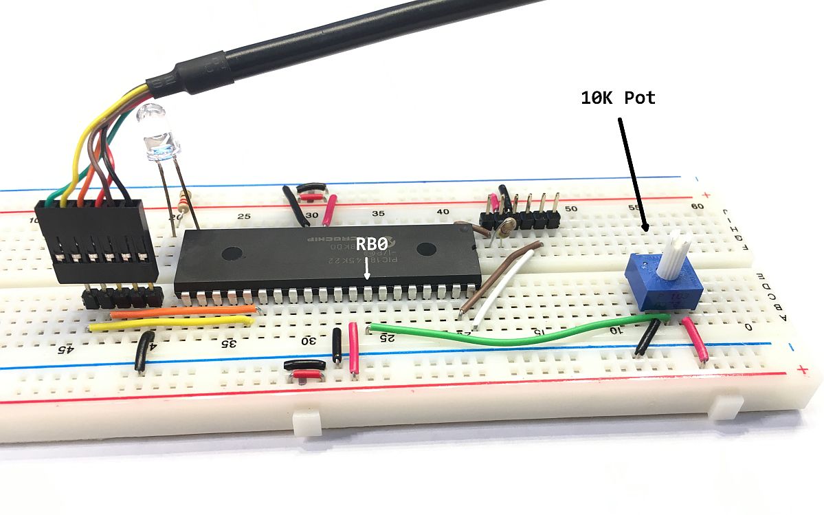
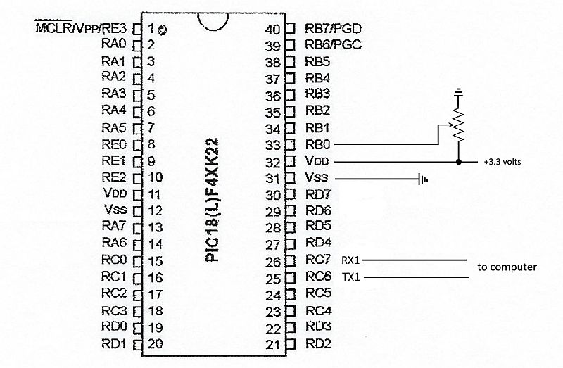
This first step to programming a microcontroller to perform ADC is to identify the pins on the micro that are ADC capable. The Analog column of Table 2 on pages 9 and 10 of the PIC18F45K22 datasheet identify which pins are equipped with analog-to-digital converters. For this project, I will use analog channel AN12 which corresponds to RB0 (pin 33) of PORTB. The following image shows the simple schematic for this project. The center pin on a 10K pot is connected to RB0. RC6 is the USART1 serial TX which will transmit the data to a connected computer.
For each port on the PIC18F45K22 there is a corresponding data direction register. For PORTB this register is named TRISB. Setting a TRISB bit will make the corresponding PORTB pin an input, and clearing a PORTB bit will make the corresponding pin an output. Table 10-5 on page 141 of the PIC18F45K22 datasheet shows that setting RB0 will configure the pin as an input. Add the following line of code to the code from the previous pic project inside the main function to configure the first bit of PORTB, RB0 pin 33 as an input pin.
TRISB = 0b00000001;// Set the first bit, RB0 as an inputEach port also has an analog select register that allows for individual control of the digital input buffers on pins which have analog capability. This register is called ANSELB for PORTB. Setting an analog capable bit enables the analog functionality of that pin. The following line of code sets RB0, pin 33 as an analog pin. Add this line of code inside the main function.
ANSELB = 0b00000001;// Configure pin33 RB0 (AN12) as analogWith the port configuration code complete, it's time to configure the ADC. The Microchip peripheral library which is included with the version 1.35 XC8 compiler, makes configuring the analog-to-digital converter easy. The library contains a funtion named OpenADC which configures the analog-to-digital converter. Note that if you are using a newer version of the XC8 compiler, you may have to use the MPLAB Code Configurator (MCC) software to configure the ADC peripheral. The three bitmask parameters of the OpenADC function configure the ADC. When calling the function pass the configuration arguments by performing either bitwise AND operations or bitwise OR operations. The Peripheral Help document that comes with the XC8 compiler describes the various functions that setup, configure, or control peripheral modules on the PIC. Also, section 17 of the PIC18F45K22 datasheet describes the ADC in detail. Add the following code inside the main function to configure the ADC.
    /*Configure the A/D converter*/

    OpenADC(ADC_FOSC_2 & ADC_RIGHT_JUST & ADC_12_TAD,

            ADC_CH12 & ADC_INT_OFF,

            ADC_TRIG_CTMU & ADC_REF_VDD_VDD & ADC_REF_VDD_VSS);
The first argument passed to OpenADC selects the A/D clock source, sets up the A/D result bit justification, and sets the acquisition time. The second argument selects the ADC channel and sets up the A/D interrupts. And the third argument selects the special trigger, configures the A/D positive and negative voltage reference Please read more about this in the PIC18F45K22 datasheet.
That is all there is to setting up the ADC. To actually read the voltage on pin 33, there are three steps - start the voltage capture, wait for the A/D conversion to finish and then read the result. Again, the peripheral library contains functions to complete these steps. The function SelChanConvADC starts the analog-to-digital conversion on the selected channel. The BusyADC function returns true while the ADC is busy and ReadADC reads the converted data. Since the ADC has a resolution of 10 bits the minimum value ReadADC will return is 0 and the maximum is 1024. We need to add an unsigned integer value to the code outside of the main function to hold this value.
unsigned int v; // to hold the voltage for(;;){
SelChanConvADC(ADC_CH12);// Select CH12 and start the conversion
while(BusyADC()); // Wait for A/D conversion to complete
v = ReadADC(); // Read converted data
const float volts = v * VOLTAGE/1024; // convert to volts
sprintf(str, "Volts = %f\r\n", volts); // convert to string
putrs1USART(str); // write the string out the serial port
delay_seconds(1); // wait 1 second
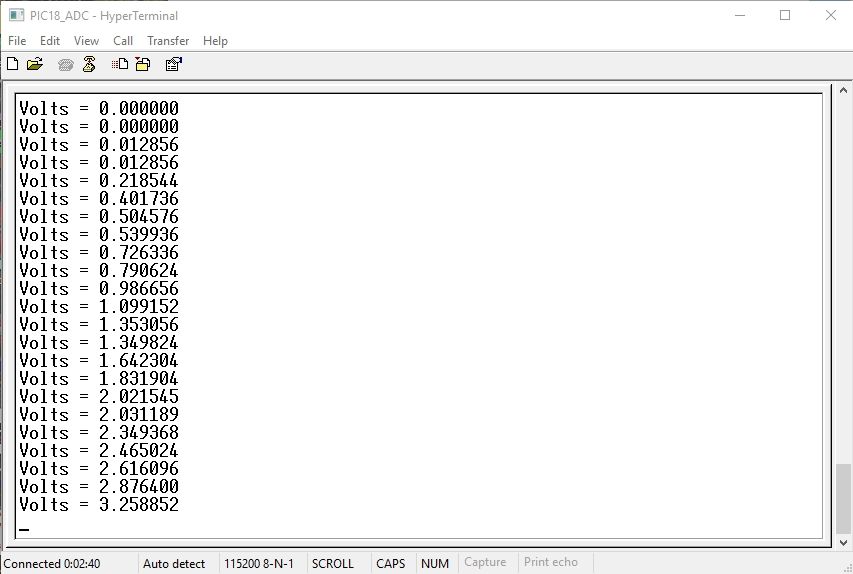
}After the reading is converted into a voltage value, this value is turned into a string and written to the serial transmit buffer using the putrs1USART function. This function is also a peripheral library function related to serial communication. It writes a string to the serial port. Please read my previous article to learn about the PIC18F45K22 USART and serial port info. I used HyperTerminal to read the serial data coming from the PIC18F45K22. The following image shows the captured serial data as I turned the potentiometer. The system voltage for my PIC is 3.291 volts. As the image shows the full range of the system voltage is being captured.
Here is the complete code.
/***********************************************
* Project Name: PIC18-ADC
* Author: Frank Mock, July 2017
* File Name: main.c
* Microcontroller used: PIC18F45K22
* Compiler used is XC8 VERSION 1.35
* Code uses the Peripheral Library, plib, by Microchip Technologies
* Description: Every second, the PIC will read a voltage at RB0 using ADC.
* This voltage will be converted to a string before it is sent
* out the serial port.
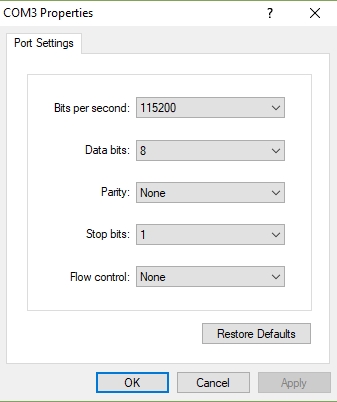
* Serial Port Settings: Baud rate 115200, 8 bit, no flow control, no stop bit
****************************/
#include< xc.h >
#include< stdio.h > // For sprintf to convert int to string
#include< plib\usart.h >
#include< plib\adc.h >
// Oscillator Selection bits (Internal oscillator block)
#pragma config FOSC = INTIO67
// MCLR Pin Enable bit (MCLR pin enabled, RE3 input pin disabled)
#pragma config MCLRE = EXTMCLR
// Watchdog Timer Enable bits (Watchdog timer is always disabled)
#pragma config WDTEN = OFF
#define _XTAL_FREQ 16000000 //speed of the internal oscillator
unsigned char c; // will hold rx value
const float VOLTAGE = 3.291;
unsigned int v; // to hold the voltage
char str[256]; //buffer to hold string
// Function prototypes
void SetUpClock();// setup internal oscillator
void interrupt isr(void); //UART receive interrupt handler
void delay_seconds(unsigned char s); //Creates delay in seconds
void FlashLEDs(); //Flashes an LED at one second intervals
int main(){
SetUpClock(); //internal clock set to 16MHz
/*Port setup for the LED*/
ANSELD = 0; //Configure PORTD as digital
TRISD = 0; //Configure PORTD as output
PORTD = 0b00000000; //initial state - PORTD all off
/*Port setup for the ADC*/
ANSELB = 0b00000001; // Configure pin33 RB0 (AN12) as analog
TRISB = 0b00000001; // Set RB0 as an input
/*Configure the A/D converter*/
OpenADC(ADC_FOSC_2 & ADC_RIGHT_JUST & ADC_12_TAD,
ADC_CH12 & ADC_INT_OFF,
ADC_TRIG_CTMU & ADC_REF_VDD_VDD & ADC_REF_VDD_VSS);
/*
* According to page 268 of the data sheet, TRIS control bits of
* RX and TX should be set to 1. USART will automatically reconfigure
* them from input to output as necessary
*/
TRISCbits.RC6 = 1;
TRISCbits.RC7 = 1;
//analog PORTC ports may interfere with serial port receive
ANSELC = 0X00; //Make all PORTC pins digital
RCONbits.IPEN = 0; //Disable using interrupt priority
INTCONbits.GIE = 1; //Enable all unmasked interrupts
INTCONbits.PEIE = 1; //Enable all unmasked peripheral interrupts
Close1USART(); //turn off USART if was previously on
//configure USART
Open1USART(USART_TX_INT_OFF &
USART_RX_INT_ON &
USART_ASYNCH_MODE &
USART_EIGHT_BIT &
USART_CONT_RX &
USART_BRGH_HIGH,
8);//8 = x. Calculated x using 16(x + 1) = Fosc / Baud Rate
// This gave me a 115,200 baud rate
for(;;){
SelChanConvADC(ADC_CH12); // Select CH12 and start the conversion
while(BusyADC()); // Wait for A/D conversion to complete
v = ReadADC(); // Read converted data
const float volts = v * VOLTAGE/1024; // convert to volts
sprintf(str, "Volts = %f\r\n", volts); // convert to string
putrs1USART(str); // write the string out the serial port
delay_seconds(1); // wait 1 second
}
}
/*IRCF<2:0> Set Up Internal RC Oscillator Frequency Select bits
* 111 = HFINTOSC - (16 MHz) SEE PAGE 32 OF DATASHEET
*/
void SetUpClock(){
OSCCONbits.IRCF0 = 1;
OSCCONbits.IRCF1 = 1;
OSCCONbits.IRCF2 = 1;
}
//UART receive interrupt handler
void interrupt isr(void){
//If the serial port has received a byte
if((PIR1bits.RC1IF == 1)&&(PIE1bits.RC1IE == 1)){
// Read the byte received
c = Read1USART();
// Transmit what was received out the serial port
Write1USART(c);
//Clear ISR flag
PIR1bits.RC1IF = 0;
}
}
/* Creates delay in seconds
* parameter s is the number of seconds */
void delay_seconds(unsigned char s){
unsigned char i,j;
for(i = 0; i < s; i++){
for(j = 0; j < 100; j++)
__delay_ms(10);
}
}
//Flashes an LED at one second intervals
void FlashLEDs(){
for(int i = 0;i < 2; i++){
PORTDbits.RD1 = 1; //LED 1 ON
delay_seconds(1);
PORTDbits.RD1 = 0; //LED 1 OFF
delay_seconds(1);
}
}As you can see, all the code from the previous article is in place, but not necessarily used. For instance, in this project I do not flash the LED. Being able to read analog voltages with your PIC will prove to be very useful for a broad range of projects. Imagine the possibilities. For example, a weighted pendulum can be connected to a potentiometer to identify when a robot is moving up or down a ramp, or is about to tip over. A temperature sensor is another common application where a microcontroller will need to use analog-to-digital conversion. I hope this project inspires you to give PIC ADC programming a try. Feel free to ask questions or send comments using my contacts page. Thanks for reading.
The above code can be viewed and downloaded from my GitHub code repositoryGo to GitHub