I decided to use the BX-24 microcontroller due to its relatively small size and ease of programming. The BX-24 is programmed in BasicX which is very similar to Microsoft's Visual Basic. The program will include code to get the time measurements out of the microcontroller and into a personal computer via the serial port. After working out the pseudo code, I wrote the following BasicX program:
Option Explicit

'Shutter Timer Program


	'Define Variables

	Dim startTm as Single, endTm as Single, elapsedTm as Single

	Dim lightDetected as Boolean

	Dim outputBuffer(1 to 45) as byte

	Dim inputBuffer(1 to 13) as byte

	Dim myString as string


Public Sub Main()


    'Initialize Variables

    lightDetected = False

    'Set RTC to midnight for more precise calculation

    Call PutTime(0, 0, 0.0)


	'Open the input and output buffer

	call openQueue(outputBuffer,45)

	call openQueue(inputBuffer,13)


	'Define which pins we'll use for serial in and out (TX 11, RX 12)

	call defineCom3(12,11,bx1000_1000)

	call openCom(3, 9600,inputBuffer,outputBuffer)


	'Clear terminal screen - the ASCII for dec 12 is FF (which clears the terminal screen

	call putQueueStr(outputBuffer,chr(12))


	'Start Main Loop

	Do


		Do While lightDetected = false


            If getpin(13) = 1 Then       'If pin 13 has 5 volts (light is detected)

                startTm = Timer          'start the timer

			  myString = "Light Detected: "&cstr(getPin(13))

			  call putQueueStr(outputBuffer,myString)

			  'Append carriage return and line feed

			  call putQueueStr(outputBuffer, chr(10)&chr(13))

                lightDetected = True     'Break out of while loop


            End If

		Loop


        If getpin(13) = 0 Then           'If pin 13 has 0 volts (no light detected)


            endTm = Timer

		   myString = "No Light Detected: "&cstr(getPin(13))

            elapsedTm = endTm - startTm  'Calculate elapsed time

            lightDetected = False        'Reset variable back to false

		   call putQueueStr(outputBuffer,myString)

		   'Append carriage return and line feed

		   call putQueueStr(outputBuffer, chr(10)&chr(13))

		   call putQueueStr(outputBuffer, Cstr(elapsedTm))

		   'Append carriage return and line feed

		   call putQueueStr(outputBuffer, chr(10)&chr(13))


        End If


	Loop


End Sub
This program will start the BX-24 timer if 5 volts is detected at pin 13 and stop the timer and calculate the elapsed time when pin 13 returns to 0 volts. The BX-24 RTC (Real Time Clock) and Timer function is used for this. The BX-24 manual describes this function as returning the elapsed time since midnight. And also mentions that the resolution depends on the time of day. Best case resolution is about 1.95ms (1/512 seconds). This is useful information which I will come back to soon. Since the RTC is the most accurate the closer it is to midnight, I use the PutTime function to reset the clock to midnight before the timer starts. A message and the elapsed time are sent out the COM3 serial port of the BX-24.
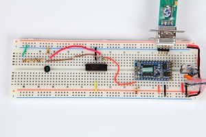
Next, it was time to build the circuit to interface with the BX-24. The most important part of this circuit is the light sensor. The light sensor will serve the purpose of starting and stopping the microcontroller's timer as it detects light changes. Think light activated switch. This is what switches the 5 volts on and off at the BX-24's pin 13. Most vintage cameras do not have shutter speeds faster than 1/500th sec. which is nearly the best case resolution for the BX-24 RTC. With this in mind, I will use this shutter timer only for speeds slower than 1/500 sec. to provide a buffer and hopefully obtain more accurate results. The shutter I used for test purposes is a Prontor-SVS with 1/300th of a second marked on it as the maximum shutter speed. The remaining speeds listed in reverse order are 1/100, 1/50, 1/25, 1/10, 1/5, 1/2 and 1 second (a bulb setting is also included). Most of my vintage cameras date from the 1920's to the 1960's. Based on the standards of this time, shutter speeds were generally considered satisfactory if they fall within plus or minus 30% for speeds faster than 1/100 sec. and plus or minus 20% for speeds 1/100 sec. and slower. These tolerances applied to new and used shutters. Therefore, it's possible that the test shutter could be slightly faster than 1/300 of a second (3ms).
The ubiquitous Cds cell or photoresistor, was the first photo sensor I did circuit testing with. Most of the Cds cell datasheets I reviewed listed a rise time of 35ms or greater at 10 lux. This of course is much slower than the 3ms the circuit would require. However, a Cds cell response time varies depending on incident light intensity, ambient temperature, light history and other factors. I was able to reduce the response time of the CdS cell in the circuit by shining a bright LED flashlight into the lens of the shutter assembly which made the incident light much greater than 10 lux. I also increased the circuits load resistance until I achieved the fastest response times, which inversely affected the measured times. The faster the circuit responded to light, the greater the recorded times. I'm not sure what the final response time was but the circuit had no problem detecting light at the fastest shutter speed of the test shutter assembly.
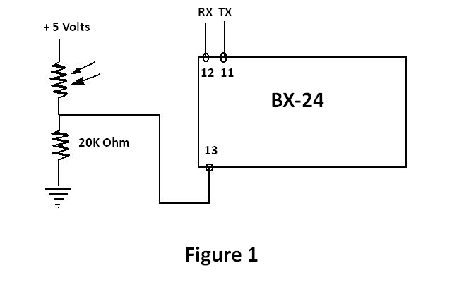
Figure 1 shows the schematic of the circuit using the photoresistor:
Next, I turned my attention to the Sharp BS120 photodiode. The datasheet for this photodiode listed "Electronic shutter for camera systems" as an application for this photodiode. Also, the fact that this photodiode has a spectral sensitivity akin to that of the human eye made me believe this would be a good choice. The peak sensitivity wavelength for this photodiode is 560nm which is nearly in the middle of the spectrum range of visible light for humans. Photodiodes are tuned to work with specific light wavelengths, so it is important to choose a photodiode for the wavelength you wish to detect. Not being an electrical engineer, I achieved the fastest photodiode reaction speed I could through experimentation of various component setups and by referencing component datasheets and application notes. Except for the occasional use of Ohms Law and the voltage divider formula, this did not involve any calculations to model the behavior of the photodetection system. The fastest, most sensitive photodiode circuit I could achieve is with the photodiode bootstrapped across the inputs of an op-amp. Figure 2 shows this current-to-voltage conversion circuit with the resistor values I found to produce the best results. This setup operates the photodiode without bias, which results in less influence by dark current and a very linear response to the intensity of incident light. Just as with the CdS cell, I used a bright LED flashlight shinning into the lens of the shutter assembly which means of course, that this flash light will be used whenever I use this shutter tester.
Figure 2 - photodiode circuit.
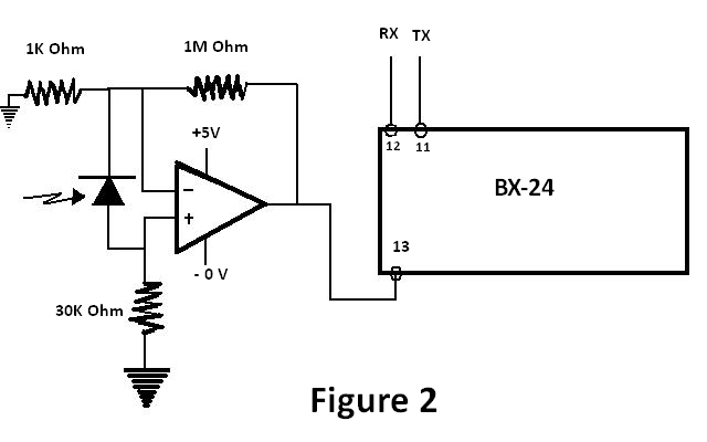
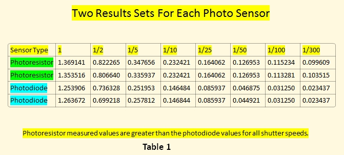
Table 1 shows some of the measured times using the CdS cell(photoresistor) circuit and the photodiode circuit. There are many more results sets for each setup. This is only a small sample of two sets for each setup. Keep in mind, the greater the recorded time, the more sensitive the light detector was to light.
There were many more test circuits besides the two I discuss above, some of which produced good results. One such circuit used a NPN transistor with the photodiode connected between the collector and base. In this circuit, the photodiode is reverse biased with 5 volts. Being reverse biased definitely improved the response time of the photodiode, but also reduced sensitivity to weaker light. In the end I decided to use the circuit with the CdS cell (figure 1) since this produced the best results. I was surprised that I could not get the photodiode to react faster to the test light. The response time of the photodiode is based on the load resistance, the higher the load resistance, the slower the response time. I achieved the final circuit result simply by trying different resistor values.
Testing was done in the following manner. The shutter assembly was placed on top of a cardboard tube which was centered over the light sensor. The distance from the lens on the shutter assembly to the light sensor was two inches. The LED light source was carefully placed directly on top of the lens of the shutter assembly. The BX-24 circuit was connected to my laptop and HyperTerminal was used to capture the incoming serial data to file. All testing was conducted in this manner.
To use this test circuit on a shutter assembly still mounted on a camera body, the 2 inch distance would have to be maintained since the light intensity has a direct effect on response time. Removing the CdS cell from the breadboard and soldering it to fine gauge wire would allow placement of the CdS cell inside the camera. Securing it inside the camera could prove to be a little tricky but nothing a creative mind couldn't handle.
As I learn more about building photometric circuits and with more electrical tinkering experience, perhaps one day I will fine tune the shutter timer circuit. If you wish to share any ideas about this project, please go to my comments page and send me a note. A smaller microcontroller such as a Pic model might be a good starting point. If I get real ambitious, why not make it wireless? I understand the ZigBee protocol is pretty easy to interface with using a XBee. And one more thing, instead of using HyperTerminal, why not build a program to not only capture the measured times but control the timer too. These are all just ideas that are fun to think about for now. I learned a great deal from this project and only wish I had more time to experiment, but I must move on. I have too many other ideas I would love to work on and such little time!
