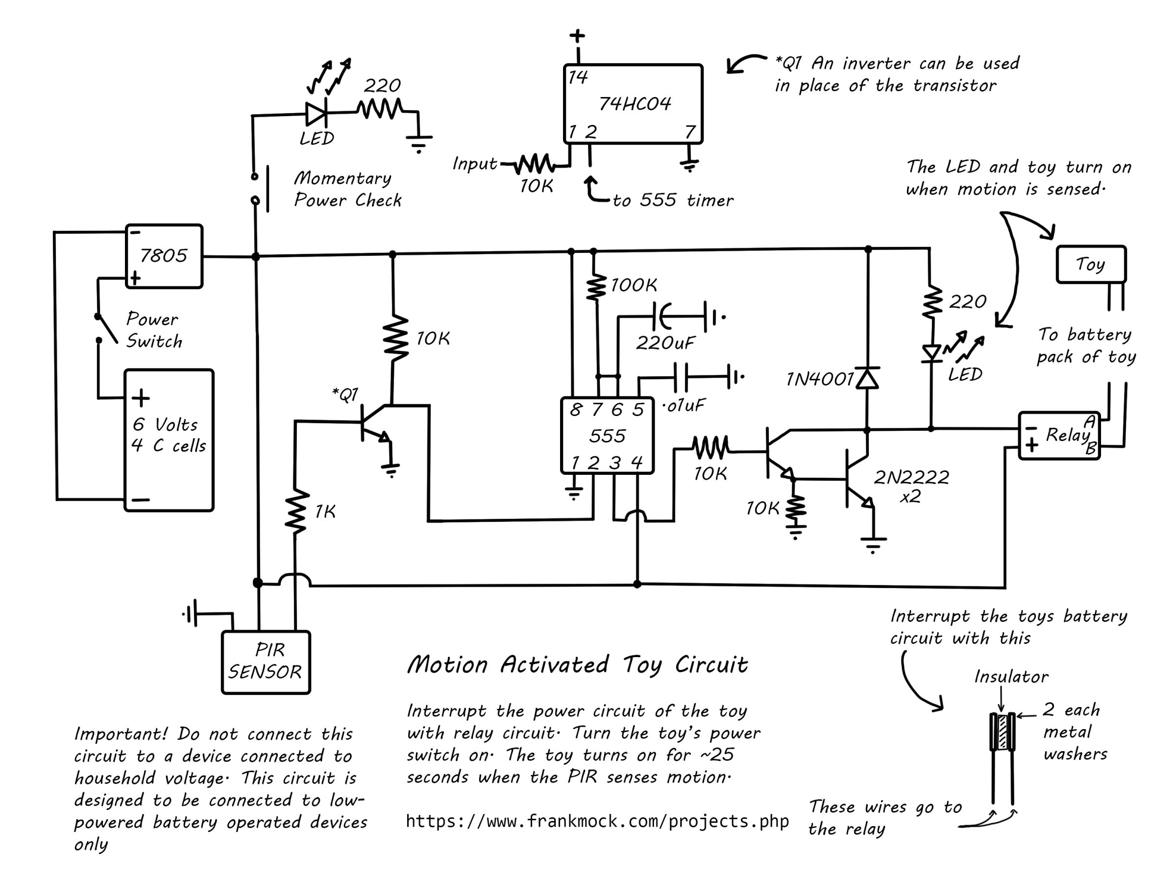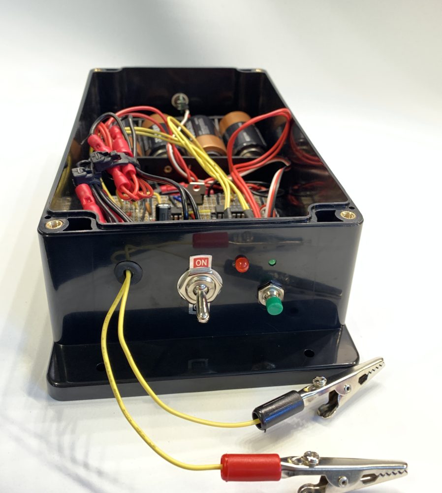
This project will show you how to activate a battery operated toy when motion is sensed in front of it. Use it to turn on a toy when trick-or-treaters approach your front door. Or use it as a "guard" to activate a loud toy or siren when someone walks into a room. The circuit is designed to turn off the toy after approximately 25 seconds. This simple circuit is designed to connect to low-power battery operated devices, not to devices connected to household voltages.
The following is a brief explanation of how this circuit works. Please refer to the schematic drawing below. At the heart of this circuit is a 555 Timer setup in monostable mode. In this configuration, the 555 timer is triggered by a negative-going pulse. When the PIR sensor senses motion it sends a small voltage to the base of the Q1 transistor. This causes current to flow through the transistor and pulls pin 2 (the trigger pin) of the 555 timer low. This in-turn causes a small voltage to flow out of pin 3 of the timer to the base of a transistor. This transistor works with another to source enough current to turn on an LED and close the relay which turns on the toy. Once the 555 timer is triggered, the output will remain high until the set time determined by the resistor and capacitor connected to pins 7 and 6 respectively. Using different values for this resistor and capacitor will change the amount of time the 555 timer remains activated. And thus, the amount of time the toy remains on.
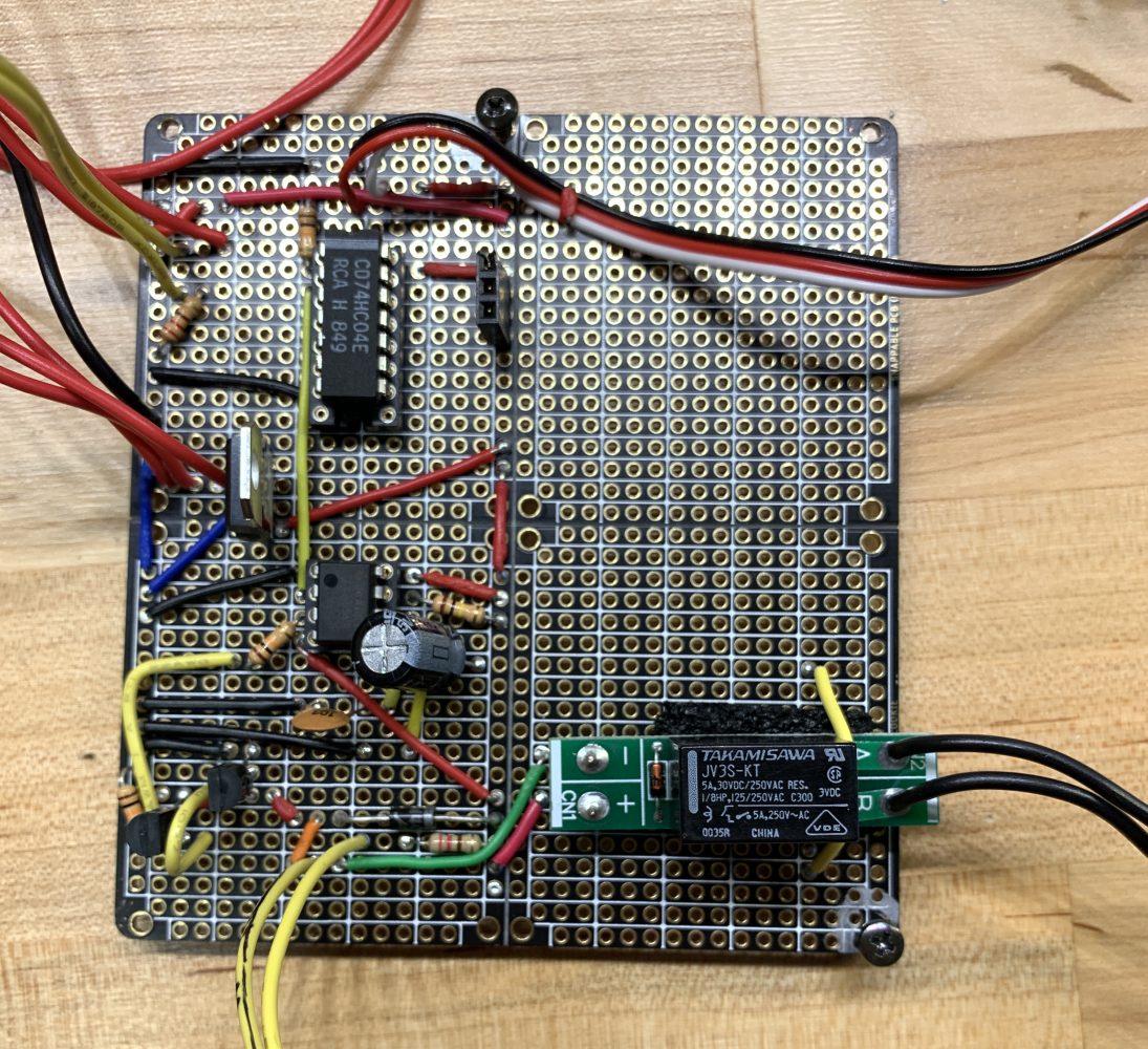
If you are running short on NPN transistors, you can substitute the Q1 transistor with an inverter. In the image below of the circuit components on the board, you can see that is exactly what I did. The diode in parallel with the "toy-on" LED serves to protect the transistors by providing a path for current as the magnetic field of the relay coil collapses. I connected the relay to a toy by soldering two metal washers to the output wires of the relay. These washers sandwich a thin piece of foam insulator material. I then disrupt the flow of voltage in the toy's battery compartment with the washer and foam sandwich. Be sure to turn the switch of the toy to the "On" position. It should not turn on until the two wires connected to the sandwich are connected (as is the function of the relay). I hope you find this circuit useful. Have fun with it!